
*lecture (Computer System Architecture)
*notes
A different interface may have to be designed for every combination of I/O device and computer, resulting in many different interfaces. The most practical solution is to develop standard interface signals and protocols.
I/O Hardware
The processor, main memory, and I/O devices can be interconnected by means of a common bus whose primary function is to provide a communications path for the transfer of data.
putting I/O devices into ‘boxes’ we typically have:
- Storage devices (disks, tapes, etc.)
- Transmission devices (network cards, modems)
- Human-interface devices (screen, keyboards, mice, joysticks…)
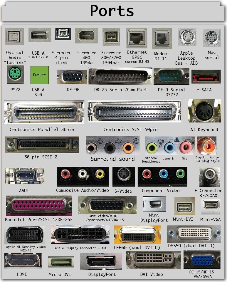
Devices all communicate over cables (or air) with the machine using ‘standard’ connections:
- Ports,
- Buses (daisy chained or shared host adaptor), and
- Device Controllers
Bus protocol
Is the set of rules that govern the behavior of various devices connected to the bus as to when to place information on the bus, assert control signals, and so on.
The bus lines used for transferring data may be grouped into three types:
- data
- address
- control lines
Synchronous bus
In a synchronous bus, all devices derive timing information from a common clock line. Equally spaced pulses on this line define equal time intervals.
Timing of an input transfer on a synchronous bus
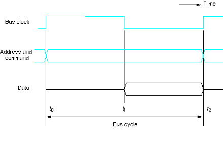
Strobe
Means to capture the values of the data at a given instant and store them into buffer.
Timing Diagram
The timing diagram is figure above is an idealized representation of the actions that take place on the bus lines.
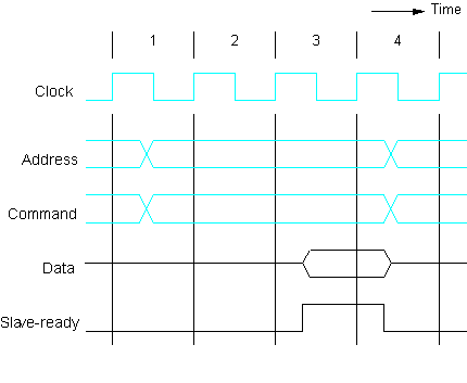
Multiple-Cycle transfers
The processor has no way of determining whether the addressed device as actually responded. It simply assumes that, at t2, the output data have been received by the I/O device or the input data are available on the data lines.
Slave-ready signal
Ia an acknowledgement from the slave to the master, confirming that valid data have been sent.
An input transfer using multiple clock cycles
Asynchronous Bus
An alternative scheme for controlling data transfers on the bus is based on the use of handshake between the master and the slave.
Concept of a handshake
Is a generalization of the idea of the Slave-ready in the figure above. The common clock is replaced by two timing control lines, Master-ready and Slave-ready.
Master-ready
Asserted by the master to indicate that it is ready for a transaction.
Slave -ready
The second which is a response from the slave.
Bus
A common set of wires connecting multiple devices. Buses include rigid protocols for the types of messages that can be sent across the bus and the procedures for resolving contention issues.
In computer architecture, a bus is a subsystem that transfers data between computer components inside a computer or between computers.
- The primary function of a bus is to provide a communications path for the transfer of data.
- A bus protocol is the set of rules that govern the behavior of various devices connected to the bus as to when to place information on the bus, assert control signals, etc.
- Three types of bus lines: data, address, control
- The bus control signals also carry timing information.
- Bus master (initiator)/slave(target)
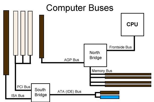
PCI bus
Connects high-speed high-bandwidth devices to the memory subsystem (and the CPU)
- Expansion Bus – Connects slower low-bandwidth devices, which typically data one character at a time (with buffering).
- SCSI bus – Connects a number of SCSI devices to a common SCSI controller.
Details of I/O Interface
An I/O interface is required whenever the I/O device is driven by the processor. The interface must have necessary logic to interpret the device address generated by the processor.
Functions of I/O Interface
- I/O interface provides a storage buffer for one word of data.
- I/O interface contains status flag that can be accessed by the processor to determine whether the buffer is full or empty.
- I/O interface contains address-decoding circuitry to determine when it is being addressed by the processor.
- I/O interface enerates the appropriate timing signals required by the bus control scheme used.
- I/O interface performs any format conversion that may be necessary to transfer data between the bus and the I/O device.
Standard I/O Interfaces
- Processor bus – Is the bus defined by the signals on the processor chip itself.
- PCI BUS – The PCI follows a sequence of bus standards that were used primarily in IBM PCs. Early PCs used the 8-bit XT bus, whose signals closely mimicked those of Intel’s 80×86 processors.
- ISA Bus – The 16-bit bus used on the PC AT computers became known as the ISA bus. Its extended 32-bit version is also known as the ISA bus.
Data Transfer
Data are transferred between the cache and the main memory in bursts of several words each. The words involved in such a transfer are stored at successive memory locations.
Three independent address spaces supported by bus:
- memory
- I/O, and
- configuration
Device Configuration

Device Configuration
When an I/O device is connected to a computer, several actions are needed to configure both the device and the software that communicates with it.
SCSI BUS
The acronyms SCSI stands for Small Computer System Interface. It refers to a standard bus defined by the American National Standards Institute (ANSI) under the designation X3.131.
Voltage Levels
-
5 V(TTL levels) – Used in earlier versions and are known as High Voltage Differential (HVD).
-
Low Voltage Differential(LVD) – A 3.3 V version that has been introduced.
Packet
May contain a block of data, commands from the processor to the device, or status information about the device.
Sector
Disk in blocks where data are stored, where each sector may contain several hundred bytes. These data may not necessarily be stored in contiguous sectors.
Initiator
Has the ability to select a particular target and to send commands specifying the operations to be performed.
The processor sends a command to the SCSI controller, which causes the following sequence of events to take place:
- The SCSI controller, acting as an initiator, contends for the control of the bus.
- When the initiator wins the arbitration process, it selects the target controller and hands over control of the bus to it.
- The target starts an output operation (from initiator to target); in response to this, the initiator sends a command specifying the required read operation.
- The target, realizing that it first needs to perform a disk operation, sends a message to the initiator indicating that it will temporarily suspends the connection between them. Then it releases the bus.
- The target controller sends a command to the disk drive to move the read head to the first sector involved in the requested read operation. Then, it reads the data stored in the sector and stored them in a data buffer. When it is ready to begin transferring data to the initiator, the target requests control of the bus. After it wins arbitration, it reselects the initiator controller, thus restoring the suspended connection.
- The target transfers the contents of the data buffer to the initiator and then suspends the connection again. Data are transferred either 8 or 16 bits in parallel, depending on the width of the bus.
- The target controller sends a command to the disk drive to perform another seek operation. Then, it transfer the contents of the second disk sector to the initiator, as before. At the end of this transfer, the logical connection between the two controllers is terminated.
- As the initiator controller receives the data, it stores them into the main memory using the DMA approach.
- The SCSI controller sends an interrupt to the processor to inform it that the requested operation has been completed.
“Higher Level” SCSI Bus
Means that the messages refer to operations that may require several steps to complete, depending on the device. Neither the processor nor the SCSI controller need be aware of the details of operation of the particular device involved in a data transfer.
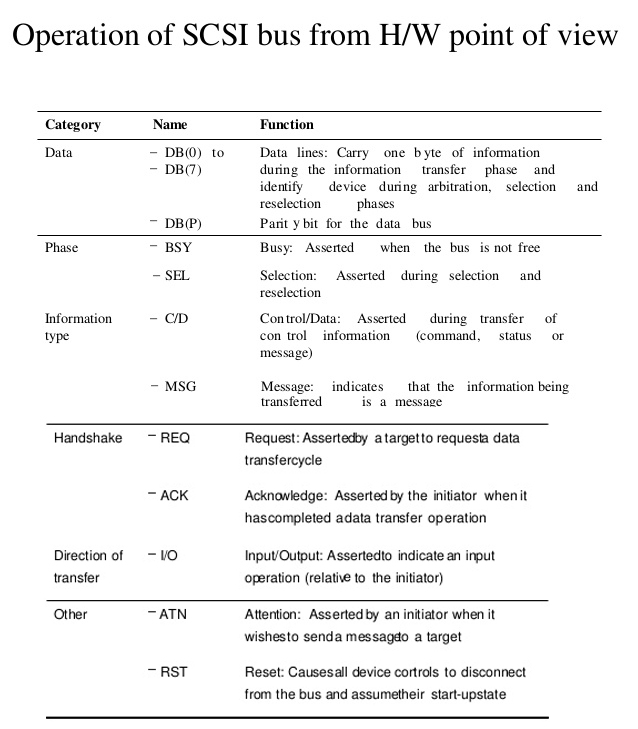
Bus Signal
The bus signal are summarized in Table below. For simplicity we show the signals for a narrow bus (8 data lines).
The SCSI bus signals 8 data lines
What is the Difference between port, bus, protocol and interfaces?
Port
A port is commonly defined as a connection point (or interface) between external hardware, like mouse, keyboard or harddrive.
Bus
A bus is a communication system that transfers data between components inside a computer.
Protocol
A protocol is a set of rules and procedures for transmitting data, aka a ‘standard’
Interface
An interface is a shared boundary between two components.
To summarize, think of an interface as basically anything that connects up two different parts, this includes a bus or port. A protocol is basically a definition of something, as set of rules everyone agreed upon so communication can be smooth. A bus is a specific kind of interface and it uses an implementation of some protocol to manage communication going through itself, so the CPU knows what to say at what time to access memory and the memory knows how to reply with data when it is requested. A port is basically a kind of external bus, right now way slower than an average bus, since speed is no bottleneck here. A port mostly connects stuff from the outside of the pc a bus connects things inside.
